Learn how to calculate the right number of stages for your submersible pump using Total Dynamic Head (TDH), flow rate, and a simple step-by-step formula for efficient water pumping.
By SLEKA Engineering Team · October 23, 2026 · 14 min read
How to Calculate the Number of Stages Needed for Your Submersible Pump
Choosing the right submersible pump involves more than selecting a motor based on horsepower (HP). One of the most important factors affecting water delivery is the number of stages in a submersible pump.
Pump stages help determine how much pressure or head a pump can develop. Selecting the correct number of stages is essential for lifting water from borewells, supplying irrigation systems, and maintaining reliable water flow in residential, commercial, and industrial applications.
In this guide, SLEKA Industries, a manufacturer of stainless steel submersible pumps, motors, and controllers, explains how to calculate the number of stages needed for your submersible pump using a simple formula, Total Dynamic Head (TDH), and practical examples.
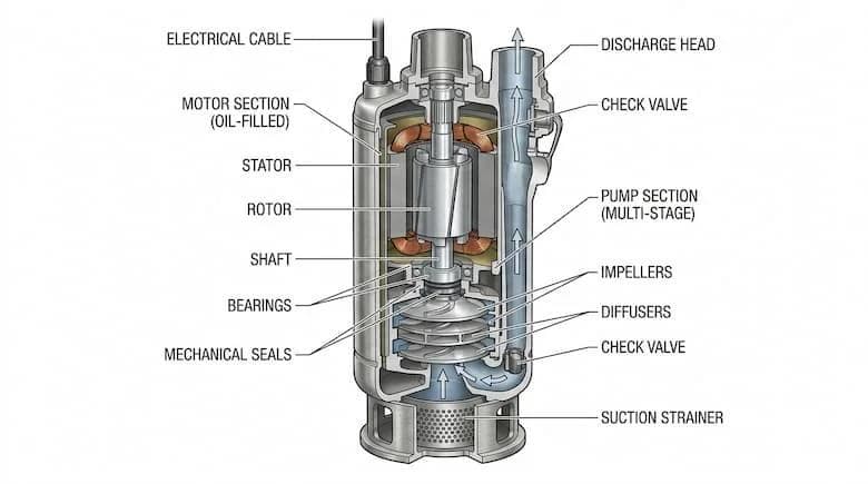
A stage in a multistage centrifugal submersible pump generally consists of an impeller and a diffuser.
The impeller transfers energy to the water, while the diffuser helps convert velocity into pressure and guides water toward the next stage.
In a multistage submersible pump, multiple impellers and diffusers are arranged in series. Each stage contributes additional head, allowing the pump to deliver water against greater pressure requirements.
For example, a pump with 10 stages can generally develop more head than a comparable pump with 5 stages operating at the same flow rate and speed.
However, the actual head depends on the pump design, impeller geometry, operating speed, and flow rate.
The number of stages influences:
It is important to understand that adding stages primarily increases head, not the pump's nominal flow capacity. Actual water delivery depends on the interaction between the pump curve and the piping system.
The basic formula is:
Number of Stages = Total Dynamic Head (TDH) ÷ Head Developed per Stage
Where:
The calculated result is rounded up to a whole number for preliminary selection. The final stage count must be confirmed using the manufacturer's pump performance curve.
Before calculating stages, identify how much water the system needs.
Flow rate is generally measured in:
For example, an irrigation system may require a flow rate of 6 m³/h.
This flow requirement is important because a pump's head per stage changes with flow rate.
Always select the pump based on both required head and water discharge.
Understanding how to calculate submersible pump stages becomes easier with practical examples. The number of stages depends on the Total Dynamic Head (TDH) and the head generated by each pump stage.
For the following examples, we assume that each pump stage produces 10 metres of head at the required flow rate.
Required TDH: 40 metres
Head per Stage: 10 metres
Calculation: 40 ÷ 10 = 4
Required Number of Stages: 4 Stages
Required TDH: 60 metres
Head per Stage: 10 metres
Calculation: 60 ÷ 10 = 6
Required Number of Stages: 6 Stages
Required TDH: 80 metres
Head per Stage: 10 metres
Calculation: 80 ÷ 10 = 8
Required Number of Stages: 8 Stages
Required TDH: 100 metres
Head per Stage: 10 metres
Calculation: 100 ÷ 10 = 10
Required Number of Stages: 10 Stages
Required TDH: 120 metres
Head per Stage: 10 metres
Calculation: 120 ÷ 10 = 12
Required Number of Stages: 12 Stages
Required TDH: 150 metres
Head per Stage: 10 metres
Calculation: 150 ÷ 10 = 15
Required Number of Stages: 15 Stages
Important Note: These calculations are illustrative. Actual head per stage varies depending on pump design, flow rate, and operating conditions. Always refer to the manufacturer's pump performance curve before selecting the final number of stages.
Suppose an agricultural borewell pumping system requires:
Formula: Number of Stages = TDH ÷ Head per Stage
Calculation: 100 ÷ 8 = 12.5
Preliminary Selection: 13 Stages
Since partial stages cannot be installed, the result is rounded up to the next whole number. The final selection should be verified using the actual pump performance curve.
Different submersible pump models produce different amounts of head per stage.
For example, one pump design might deliver 7 metres per stage at a particular flow, while another may deliver 10 metres per stage at the same flow.
The actual value must be checked from the manufacturer's technical catalogue or performance curve.
For this calculation example, assume the selected pump develops 10 metres of head per stage at the required discharge.
This value is illustrative, not a specification for a particular SLEKA pump model.
Using the formula:
Number of Stages = TDH ÷ Head per Stage
Suppose:
Calculation:
Number of Stages = 70 ÷ 10 = 7 stages
The preliminary calculation indicates that a 7-stage pump configuration may satisfy the head requirement.
Before finalising the selection, verify that the actual pump delivers the required flow at 70 metres of head, that the motor can support the required power, and that the pump operates within its recommended performance range.
Understanding how to calculate submersible pump stages becomes easier with practical examples. The number of stages depends on the Total Dynamic Head (TDH) and the head generated by each pump stage.
For the following examples, we assume that each pump stage produces 10 metres of head at the required flow rate.
Required TDH: 40 metres
Head per Stage: 10 metres
Calculation: 40 ÷ 10 = 4
Required Number of Stages: 4 Stages
Required TDH: 60 metres
Head per Stage: 10 metres
Calculation: 60 ÷ 10 = 6
Required Number of Stages: 6 Stages
Required TDH: 80 metres
Head per Stage: 10 metres
Calculation: 80 ÷ 10 = 8
Required Number of Stages: 8 Stages
Required TDH: 100 metres
Head per Stage: 10 metres
Calculation: 100 ÷ 10 = 10
Required Number of Stages: 10 Stages
Required TDH: 120 metres
Head per Stage: 10 metres
Calculation: 120 ÷ 10 = 12
Required Number of Stages: 12 Stages
Required TDH: 150 metres
Head per Stage: 10 metres
Calculation: 150 ÷ 10 = 15
Required Number of Stages: 15 Stages
Important Note: These calculations are illustrative. Actual head per stage varies depending on pump design, flow rate, and operating conditions. Always refer to the manufacturer's pump performance curve before selecting the final number of stages.
Suppose an agricultural borewell pumping system requires:
Formula: Number of Stages = TDH ÷ Head per Stage
Calculation: 100 ÷ 8 = 12.5
Preliminary Selection: 13 Stages
Since partial stages cannot be installed, the result is rounded up to the next whole number. The final selection should be verified using the actual pump performance curve.
Suppose an agricultural borewell pumping system requires:
The calculation is:
100 ÷ 8 = 12.5 stages
Since partial stages cannot be installed, the preliminary result is 13 stages.
The pump manufacturer's available configurations and head-discharge curves must then be checked to confirm the correct model.
Although the formula is straightforward, several operating conditions influence the final pump selection.
The deeper the pumping water level, the greater the static lift required to deliver water to the surface.
Seasonal groundwater fluctuations can also change the pumping conditions, so the lowest expected operating water level should be considered during system design.
A submersible pump must provide the desired water flow at the required head.
A pump producing sufficient head at low flow may not provide the same head when a higher discharge is required.
Therefore, the operating point on the head-discharge curve is essential.
Long pipelines, undersized pipes, elbows, and valves can increase friction losses.
Higher friction losses increase the total head requirement and may influence the required stage count.
Pumping water to an elevated tank or operating a sprinkler system may require additional head.
The calculation should include the actual elevation difference and pressure required at the delivery point.
The pump motor must be appropriately sized for the selected hydraulic duty.
Increasing the number of stages can increase the power required to drive the pump. Motor selection must consider flow, head, pump efficiency, and operating conditions.
In solar pumping applications, pump performance can vary with motor speed and the available solar power.
Understanding the relationship between pump head, horsepower, stages, and flow rate is essential for selecting the right submersible pump.
Pump head represents the energy supplied to water per unit weight. It determines the pump's ability to overcome elevation differences, pressure requirements, and pipeline losses.
Horsepower represents the motor's power rating. Motor power must be suitable for the required pump flow, head, and efficiency.
Stages are the hydraulic sections arranged in series inside a multistage pump. Additional stages generally increase the total head developed.
Flow rate represents the quantity of water delivered over time. It is commonly measured in litres per minute or cubic metres per hour.
Important: A higher HP motor does not automatically mean higher pump head or greater water discharge. Correct pump selection requires matching the flow rate and Total Dynamic Head with the manufacturer's performance curve.
There is no universal stage count for a particular horsepower rating.
Two 5 HP submersible pumps may have different stage counts because they are designed for different combinations of flow and head.
One pump may prioritise higher water discharge at moderate head, while another may be designed for higher head at lower discharge.
To select a pump correctly, check:
The correct number of stages depends on the hydraulic duty, not simply the motor HP.
A borewell may be 150 metres deep while the pumping water level is much shallower. Using the complete depth as vertical lift can result in incorrect pump sizing.
Long delivery pipelines and restrictive fittings create resistance. Ignoring these losses can result in insufficient pressure or water delivery.
Different pump designs have different hydraulic performance curves. A generic head-per-stage assumption should never replace manufacturer data.
Motor HP alone cannot determine the correct combination of pressure and flow.
Oversizing can result in unwanted pressure, higher power demand, or operation outside the recommended performance range.
Instead of automatically adding extra stages, calculate appropriate design allowances and review the complete system.
At SLEKA Industries Pvt. Ltd., we manufacture stainless steel submersible pumps, submersible motors, and pump controllers for agricultural, residential, commercial, and industrial water pumping applications.
Our stainless steel submersible pump portfolio includes 4-inch, 6-inch, and 8-inch pump series designed for different flow and head requirements.
We also offer solar pumping solutions and matched Pump, Motor & Controller (PMC) configurations.
Selecting the right pump involves matching the required flow and Total Dynamic Head with the manufacturer's performance data.
Our team can assist dealers, EPC contractors, distributors, OEM buyers, and project customers with product selection based on their pumping requirements.
Divide the Total Dynamic Head by the head developed per stage at the required operating flow rate. Round up to a whole number for preliminary sizing and verify the result against the manufacturer's performance curve.
In a typical multistage centrifugal submersible pump, one stage consists of an impeller and a diffuser. The stage adds head as water passes through the pump.
There is no fixed value. Head per stage depends on the impeller design, operating speed, and water flow rate. Refer to the technical catalogue of the selected pump.
Additional stages primarily increase the available head. Actual water flow depends on the pump curve and the system resistance. More stages do not automatically increase the pump's rated discharge capacity.
If a selected pump develops 10 metres of head per stage at the required flow, approximately 10 stages are needed. If it develops 8 metres per stage, the preliminary calculation gives 13 stages. The final selection must be verified using the pump curve.
The basic hydraulic principle remains applicable. However, solar pump operating speed and available power may vary. Stage selection should use performance data corresponding to the intended speed and operating conditions.
No. A higher stage count is suitable only when the system requires the additional head. Selecting unnecessary stages can result in an inefficient or unsuitable installation.
Identify your required water discharge, pumping water level, delivery height, pipe losses, borewell diameter, and power supply. Use this information to compare manufacturer pump curves or consult a technical pump supplier.
Understanding how to calculate the number of stages needed for a submersible pump helps you select a pumping system that meets the required water flow and delivery pressure.
The basic calculation is simple:
Number of Stages = Total Dynamic Head ÷ Head per Stage
However, reliable pump selection requires accurate water-level measurements, pipeline calculations, operating flow requirements, and manufacturer performance data.
Choosing the right combination of pump stages, motor power, and controller can support efficient and dependable operation.
SLEKA Industries provides stainless steel submersible pumps, motors, and controllers for a range of pumping applications.
Share your borewell depth, pumping water level, required head, flow rate, and application with our team to discuss a suitable pumping solution.
Contact SLEKA Industries Pvt. Ltd.
Website: https://slekaind.com/
Email: marketing@slekaind.com
Phone: +91 93212 76302
Contact our team for product specifications, technical guidance, or bulk project enquiries.